
The BBC and Master Computer Public Domain Library
Fitting DFS to a Tape Only BBC B
Fitting an 8271 DFS to a Tape only BBC
I provide the following instructions in good faith. Please let me know if any of it is incorrect so that I may correct it. Please do not attempt to undertake making any of the following modifications if you are not confident that you can do it safely. Please be careful with your BBC. I can offer to fit the upgrade for you if you wish. If you damage your machine accidentally or due to error in the following text, I am very sorry, but please don't expect me to take responsibility (just let me know).
Break Link S9
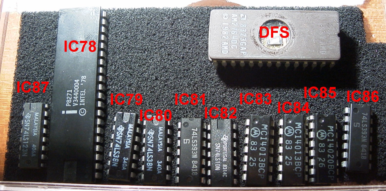
IC 87 Fit 741S123
IC 78 Fit 8271
IC 79 Fit SN7438N
IC 80 Fit RS7438
IC 81 Fit 74LS393
IC 82 Fit 74LS10
IC 83 Fit 4013B
IC 84 Fit 4013B
IC 85 Fit 4020B
IC 86 Fit 74LS393
Fit DFS inbetween MOS and Basic
More detailed info:
The 8271 fitting kit should contain the following:
2 x CD4103B (IC83,84)
2 x 7438 (IC 79,80)
2 x 74LS393 (IC81,86)
1 x CD4020B (IC85)
1 x 74LS10 (IC82)
1 x 74LS123 (IC87)
1 x 8271 (IC78)
1 x 2764 (Disc Operating System EPROM)
Switch off and disconnect the computer from the mains supply.
Remove the top cover by two screws marked 'FIX' at the rear of the machine and two screws marked 'FIX' fitted underneath the machine below the keyboard.
Remove the keyboard held by two bolts. Disconnect the ribbon cable from the cable and speaker lead too.
Wiring changes:
IMPORTANT: This section contains a wiring modification that must be
carried out on Issues 1-3 printed circuit boards (the issue number is clearly
printed on the circuit board. Issue 4 boards onwards DO NOT NEED the following
modifications.
1) Carefully cut the leg (pin 9) of IC27 and lift it clear of the solder
pad.
2) Cut the track between pin 9 pad and 'S9' link by making a single
cut in the track with a small modelling knife
3) Solder a thin piece of insulated wire between pin 9 of the IC leg
and 'S9' (right hand pad).
4) On issue 1 or 2 boards only, add a wire link in position S8
Set the following link positions using shorting links:
S18 North
S19 East
S20 North
S21 East/West (two links)
S22 North
S32 West
S33 West
S12 Cut Link
S13 Cut Link
On issue 4 boards onwards, remove link S9
Fit ICs 78, 79, 80, 82, 81, 86, 83, 84, 85, 87 into the sockets provided making sure the orientation of each IC is correct with the small pip on the chip surface facing the back of the circuit board (in the same direction as all the other chips on the board)
Check that none of the chip legs are bent over whilst inserting.
Fit the disc operating system ROM in the fourth position from the left in the block of 5 x 28 pin sockets.
It would be useful to move the BASIC from the second to the third position.
Refit the keyboard, speaker lead and ribbon cable. Refit the cover.
Switch on and listen for the double beep