The BBC and Master Computer Public Domain Library
Fitting a Genlock Board to a Master 128
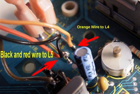
Orange wire to L4. Black wire to L5. Red wire to L5
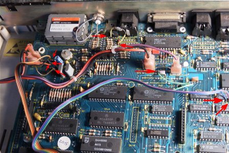
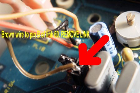
Brown wire. Remove link from link 60 and solder brown wire to pin labelled 'B'
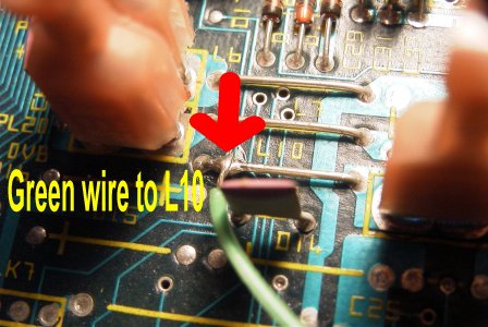
Green wire to L10
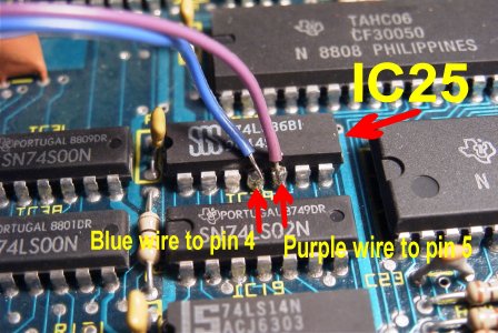
Purple wire to IC25 Pin 5. Blue wire to IC25 Pin 4
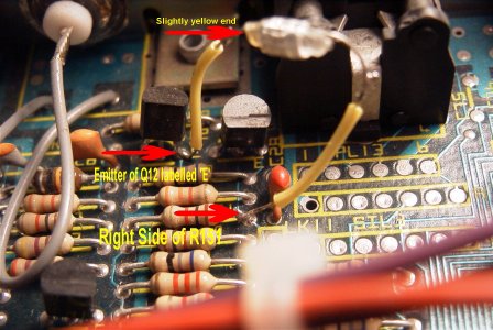
?Capacitor
This component has one end slightly yellow. The wire attached to this solders
to the emitter of Q12 (labelled 'E' on the board)
The other wire from this component solders to the right hand side of R151. Since
taking the photographs with this info, I have coloured this wire red