The BBC and Master Computer Public Domain Library
John Ilslry Moisture Detector
Moisture Detector. By: John Ilsley (27N).
Welcome to the first hands on project. I have chosen a very simple project to start with which should not cost you much more than about one pound fifty pence to make.This moisture detector will detect moisture in anything, I've tested it on everything from a jug of tap water down to damp walls, the human skin and even in a plant pot! So you could use it to see if your plants need watering.
I have taken a simple version, but by changing component 'L1' to a sensitive needle meter and changing component 'R1' a resistance value to suit the needle meter you would get a much more accurate reading.
Please note, whilst I have made every effort to make this an interesting and informative article neither 8BS, the editor or myself will accept responsibility for any damage caused to yourself, other persons, components, belongings or other equipment used in conjunction with this project.
The components you will need for the simple version are as follows.
T1 = 1 * BC184L Transistor
R1 = 1 * 1k (1000ohm) 5% resistor (see text for info on needle meters).
R2 = 1 * 1k (1000ohm) 5% resistor
L1 = 1 * 10 mA LED
BT = 1 * 9 volt radio battery or power supply unit (PSU) and leads
Veroboard = 7 holes across * 6 tracks
22swg multicore sheaved wire, solder, soldering iron etc....
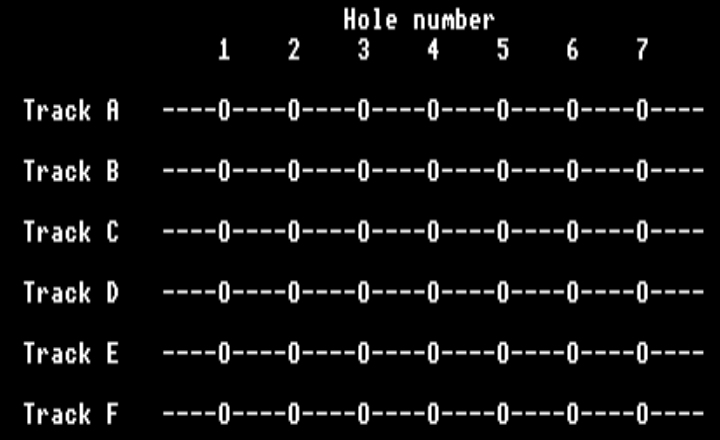
First the veroboard. Place it so the tracks are face down running left to right, similar to this:- NB( the 'Os are HOLES, '----' are tracks).
 Now comes the fairly easy bit. First we will put
in the transistor TR1
as this is the most complicated piece here. If you hold
the transistor with the
legs pointing down and the half round area of TR1 to your
LEFT then you can
place it into the board. Fine. Hold the veroboard off the
table with the tracks
below and then take TR1 and place the leg FURTHEST from
you into hole B5, the
middle leg into C5 and the leg nearest to you will go
into hole D5. Now don't
push that all the way down, leave some room other wise
you may break the legs
when soldering, or if you have to remove it. For future
reference, the legs on
this BC184L NPN transistor are as follows. The leg in B5
is called the BASE.
The middle leg in C5 is called the COLLECTOR and the leg in D5 is called the EMITTER.
Ok. Now we will add R1. This can go either way round, bend the leadout wires of this resistor 90 degrees so that if you hold the main body, both legs hang down. Place one leg into hole A3 and the other leg into hole E3. Now you can push R1 in nearly all the way, solder it in. Bend the leadout wires of R2 the same way and place one leadout wire into hole B6 and the other leadout wire into hole F6.
Now for the LED or L1. This has a positive and negative side to it. If you look into the LED you will see two very small pieces of metal, if you look closely you will see what also looks like a thin sliver of wire. However, look closely at the two pieces of metal, one is smaller than the other. This is the Anode or the positive side. The large piece of metal is the Cathode or the negative side. Place the positive side of L1 into hole E2 and the negative side into hole C2. Just push them in enough to solder them in so you have a light that is quite high.
That is the electronic components fitted in. Now we will add the probe leads. Take a piece of wire, it doesn't matter how long, about 1ft is ideal. Remove about 1/2 a centimeter from either end, twist the loose wires at either end so there are no strays and then tin them. Do this by running the soldering iron over the ends and putting a small amount of solder on the ends. You will need to tin nearly every bit of wire you use. Do the same to another 1ft piece of wire so you end up with two separate pieces of wire with each end covered in solder. Place one end of one of the wires into hole A1 and solder it in and the other wire into hole F1 and solder this in.
Now to add the power. If you have a separate 9 volt DC PSU then you won't need to do this, you can wire directly into these holes, but be warned, you do so at your own risk!
If you are using a 9 volt radio battery and connecting lead, take the red + lead and tin the end, then place it into hole A7, solder it in. Now take the black lead and place in hole D7 and solder it in.
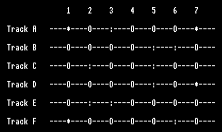
Now check that all your solder joints are clean and tidy and that no solder is bridging or going onto any of the other tracks and that all the components are in the right places. Below should give you an idea of where leads should go. The ':' are components leads, the '*' are wires. Now you can plug your battery onto the battery lead.

TESTING
The LED should not light up, If it does then make sure that the probe wires, (A1 and F1) are not touching each other. If they are not touching, then disconnect the battery and check for these, (1). T1 is fitted the correct way round. Other then that check everything.If the LED does not light up then touch the probe wires (A1 and F1) together, the LED should now glow brightly. If it does not then disconnect and check these few things.
(1). The battery supply or PSU supply is connected round the right way.
(2). That L1 is connected with the positive and negative lead in the right place.
(3). That T1 is fitted the correct way round. Other than that check everything.
If the LED lights up only when the probe wires are touched together then everything is ok. You can now test this a bit more fully, You can touch each end of the wire with your fingertips, it doesn't matter whether you lick them or not the effect is almost the same. Go to a dry plant pot and stick the leads into the soil, the LED should not glow at all or if it does, then very dimly. It is a very sensitive device, test it to see if the walls in your house or outhouse are wet, even if they feel dry to the touch.
OTHER THINGS TO TRY WITH THIS
If your'e lucky enough to own a digital or needle test meter then you can set it to a low voltage range, about 3 volts will be the maximum reading your likely to get, remove L1 and place the '+' and '-' leads of your tester into this. You will then get a reading that you can work by.This can also be connected to the analogue port on the BBC. Any channel will do but the output voltage will have to be lowered down to about 1 volt to be able enable your program to work accurately. If you're interested,
I may take this up at a later date when I turn your attentions to the BBC Userand Analogue ports.
HOW IT WORKS
So how does this work? Well it is very simple to understand which makes it simple for even the beginner to understand. When the battery is connected, current is passed to two points in the circuit, one is R1. This lowers the current to the LED so that the LED won't blow. The second is to one of the probes.Negative doesn't have a current, it is an opposite. However, for the sake of argument, negative is fed into the Emitter of T1 where it waits until the probes come into partial or complete contact whereby the current from the first probe is passed through the second and to R2 which reduces the current so that T1 won't blow.
After the current has passed through R2, the current at the Base of T1 rises from 0.5v to between 0.6v and about 3.0v depending on the dampness in this case. When the Base current rises, it opens a gate that allows current to pass from the Emitter to the Collector thereby allowing the negative 'current' to pass to the LED lighting it up.
With no connection between the two probes the battery should last for years when contact is made, only about 10 mA is used each time.
Next Month.
I have shall do an electronic switch for the next issue. This will work in that you can have a buzzer which will be quiet until two wires are touched for any length of time from a fraction of a second onward. Even when the two leads are disconnected the buzzer will sound until the power is switched off.If you have any circuits you would like me to attempt for you, please feel free to ask and I will try my best to see if I can make them for you. If they're interesting, I may make them into a project for the mag and put your name forward as the person whos idea it was.