
The BBC and Master Computer Public Domain Library
John Ilsley Low Voltage Warning System
Welcome to the fifth project in this series, oweing to lots of users asking Chris about the light pen, that took over the last issues project, but now we're back on track and things are going fine. I hope you all had a happy Christmas and a wonderful new year. While every care has been taken to ensure this project does work correctly and that parts are readily avaliable everywhere in the UK, neither 8BS, the editor, publisher or myself will be held responsible for any error in either the text or the project. Nor for any accident to either yourself, other persons, pets or other forms of life. Computers, components or other equipment connected to, used in conjunction with, or that's just hanging around. Just be careful and you won't need to try and sue us. If I've missed anything, then that's included in the exclusion as well.
Introduction to the circuit.
The low voltage warning system will basically warn you by some means if the voltage that is being fed into the circuit is lower then the rating on the zenner diode in the circuit. The project can be used in all manner of things, either as a warning that some high current using device has been switched on and suddenly drained the power, or for something as simple as a battery voltage level checker/ indicator. It has thousands of uses but has two limitations. (1) it can't really be very accurate on voltages under 5 volts DC and (2) it won't work on voltages higher then 18 volts DC. Other than that it is a very useful device for a car, boat or caravan.Parts required.
The parts you need are listed below and as you will see, there are quite a number of parts. It is a very simple circuit to make but slightly harder than the previous circuits. R1 = 27k (red, violet, red) R2 = 1.2k (brown, red, red) R3 = 1k (brown, black, red) R4 = 1.5M (brown, black, green R5 = 33k (orange, orange, red) C1 = 47uf 25 volts C2 = 100nf polyester IC1 = 555 timer IC Tr1 = BC109C (The last 'C' is not important) D1 = see text LED1 = Red LED PW1 = Power lead (+) PW2 = Power lead (-) Veroboard 24 holes per strip * 7 strips. Soldering iron, solder tools etc...Before you start.
Like I said, making the circuit is easy and I've made it easier for users now, especially if you have a printer. On the issue there is a 'Stripboard' dump program which you simply load in and run. If you print it out and cut it to size, you can draw all the parts on to the paper before you start on the veroboard. If you don't have a printer, then I'm sorry.Making the circuit.
Making the circuit is easy if not a little complicated. First off, we'll name and number the veroboard. Hold the veroboard with the copper downwards and number each track from top to bottom 1,2,3,4,5,6 and 7. Now going straight across the top, letter it A,B,C etc. through to 'X' as below. We now need to make a break in some of the holes in the copper strip and the easiest way of doing that is as follows: The holes you need to make a break in are :- N2, N3, N4, G6, H4 and K6. Get yourself a small drill, (a 1/4" drill bit is fine) and a drawing pin or something small enough to go through the holes. Now turn the board so the tracks are facing down. Get your drawing pin and count first along from left to right 'A' to the letter you require, then go down that column from '1' to the number you require. Place the drawing pin through the hole, and hold it there with your finger. Now turn the veroboard upside down so the copper tracks are facing you and place your drill right next to the point of the pin, as you remove the pin, move the drill bit into the hole. Then simply drill in just enough to break the track so current cannot pass from one side of the hole to the other. Now repeat it for the other holes.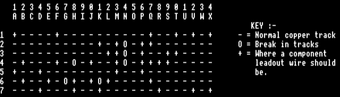
Placing all the resistors.
R1 - Place one leadout wire into hole A1 and the other wire into hole A5R2 - Place one leadout wire into hole B4 and the other wire into hole B6
R3 - Place one leadout wire into hole J4 and the other wire into hole J6
R4 - Place one leadout wire into hole S3 and the other wire into hole S4
R5 - Place one leadout wire into hole T1 and the other wire into hole T3
Placing the capacitors.
C1 - Place the (-) side wire into hole V7 and the (+) side wire into hole V1C2 - Place one leadout wire into hole R4 and the other wire into hole R7
Placing all the wire links.
Lk1 - Place one end of a piece of normal wire in K2 and the other end in K7Lk2 - Place one end of a piece of normal wire in L3 and the other end in L6
Lk3 - Place one end of a piece of normal wire in Q1 and the other end in Q2
Lk4 - Place one end of a piece of normal wire in Q4 and the other end in Q6
Placing the other bits.
IC1 - Hold the chip with the notch facing towards the top of the veroboard and place pin one of IC1 (top left pin) into hole M2. The rest should follow into holes M3, M4, M5, P5, P4, P3 and P2.TR1 - Slightly spread the legs of the transistor and hold it so the legs are facing the ground and the small tag is facing south west. One leg should be north and opposite that you should have one leg facing south with the middle leg facing east. The north leg is the collector. The middle leg is the base and the south leg is the emitter. Place the collector (north leg) into hole D5, the base (east leg) into hole E6 and the emitter (south leg) into hole D7.
LED1- Look into the bulb, and you will see that inside one bit is smaller than the other. Follow this down to the leg and place this leg into hole H6 and the other leg into H7.
PW1 - This is the (+) feed and goes into hole X1
PW2 - This is the (-) feed and goes into hole X7
As for D1, this is a Zenner diode which allows current as normal to pass only one way but when a certain 'threshold' voltage is reached, it electrically breaks until that threshold voltage is removed. Then it returns to a normal working state. So you won't have to keep replacing it as statisically they seldom break down under normal use. However you can choose any small zenner diode. I suggest you try BZY88C10V for starters, or its nearest equivalent. This has a threshold of about 10 volts. Fitting it into the circuit, take the leadout wire closest to the dark line and place it into hole F1 and the other end to F4.
How does it work?
Well, it's very simple to understand if its explained simply, so that's how I'll explain it.If a supply voltage is applied to the circuit, first it is smoothed by C1, then reduced to a current load that the circuit can handle. This is done by R1 and R5. If the current is high enough then what passes into TR1 passes through but keeps the door shut on D1 until the voltage is too low. Then the door opens on D1 and allows a circuit to be completed through it to TR1 thereby switching on IC1. With me so far?... Good!
With IC1 on, the 555 timer adjusts the time and to some extent the flash rate of LED1 but the frequency (intervals) at which the flashes occur are governed by C2. When C2 reaches IC1's threshold voltage, IC1 takes over and discharges it and this results in pin 3 going high and allowing current to pass to LED1 making it flash. So basically, if the voltage is too low for D1, then it turns on TR1 which turns on IC1 which flashes LED1.
I'm sorry I can't explain it any simpler and I'm sorry I can't explain everything for those who want to know but it is only easy to understand if it is explined simply.
Changes you can make to it.
If you want to make the flash rate quicker you could try changing C2 to a smaller value. If you wanted to make it flash slower, you could increase the value of C2. This is because the higher the value of C2 the longer it takes to charge, making the circuit in fact slow down. It's like a FOR...NEXT loop in computing, the more you increase the FOR a=1 TO xxxx the longer it takes. Reduce C2, it charges quicker and speeds up the circuit.Next months project.
I haven't yet decided on this one. I may do something for the computer and some software to go with it, or I may do one last project. If you let me know which you want then I will produce it. I'm running out of stuff for beginners. You could have mini radios, but they're too normal. Thinking about it though, if you have a secret place you want to keep locked but don't want to use a key, then I could I guess tell you how to lock it and unlock it with just a magnet. You can't use that on your disc box!Let me know which you want, another project on normal electronics, or something for the BBCs and I'll sort it out for you. Thank you to all the users who have said nice things about the projects. I'm pleased you're finding them of interest.